All the material present in this page is covered by the Creative Commons Attribution-Non commercial-ShareAlike license.
PROJECT
RGB backlight to be used in frames
AUTHORS
Walter Lain
SPECIFICATIONS
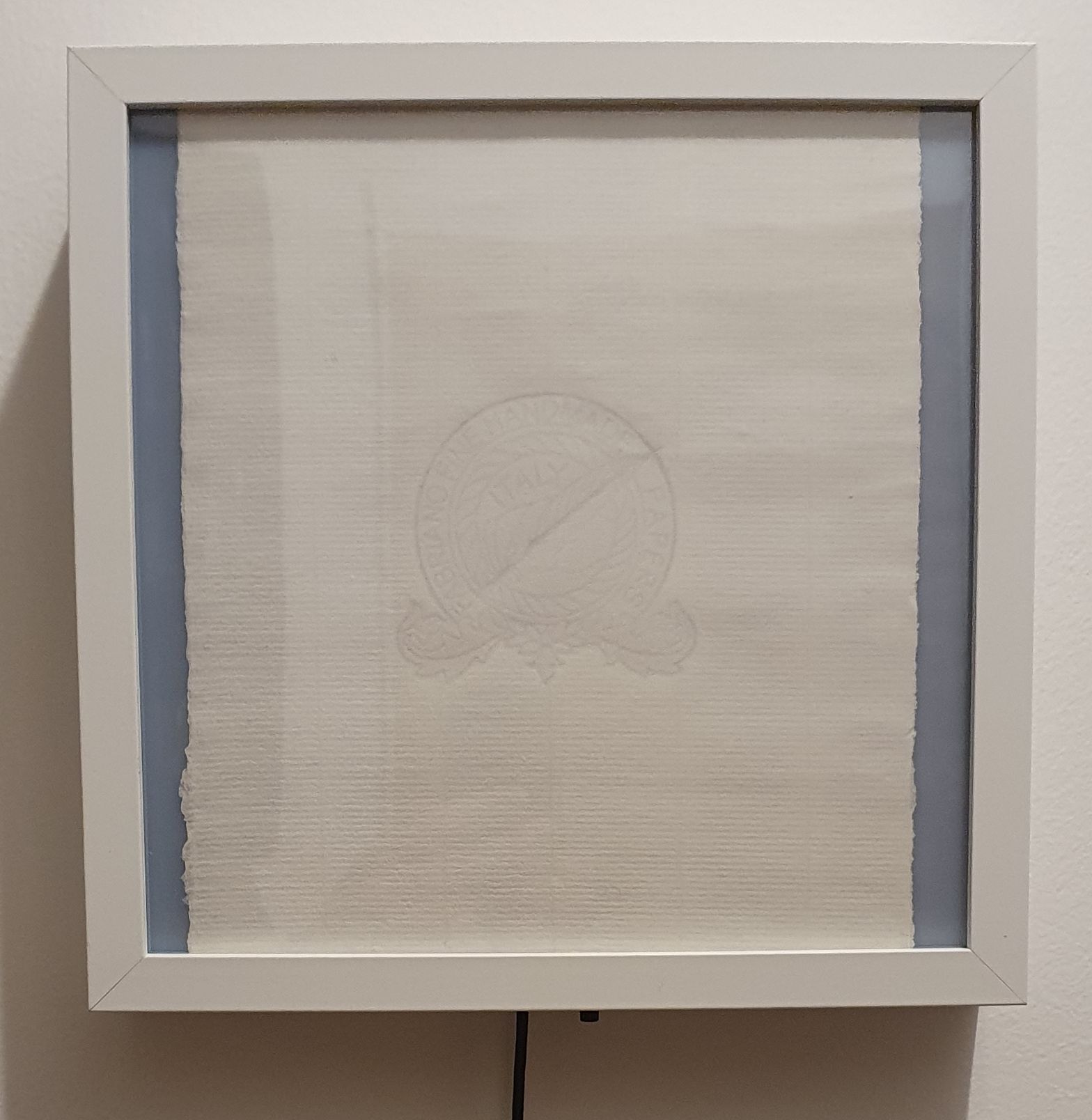
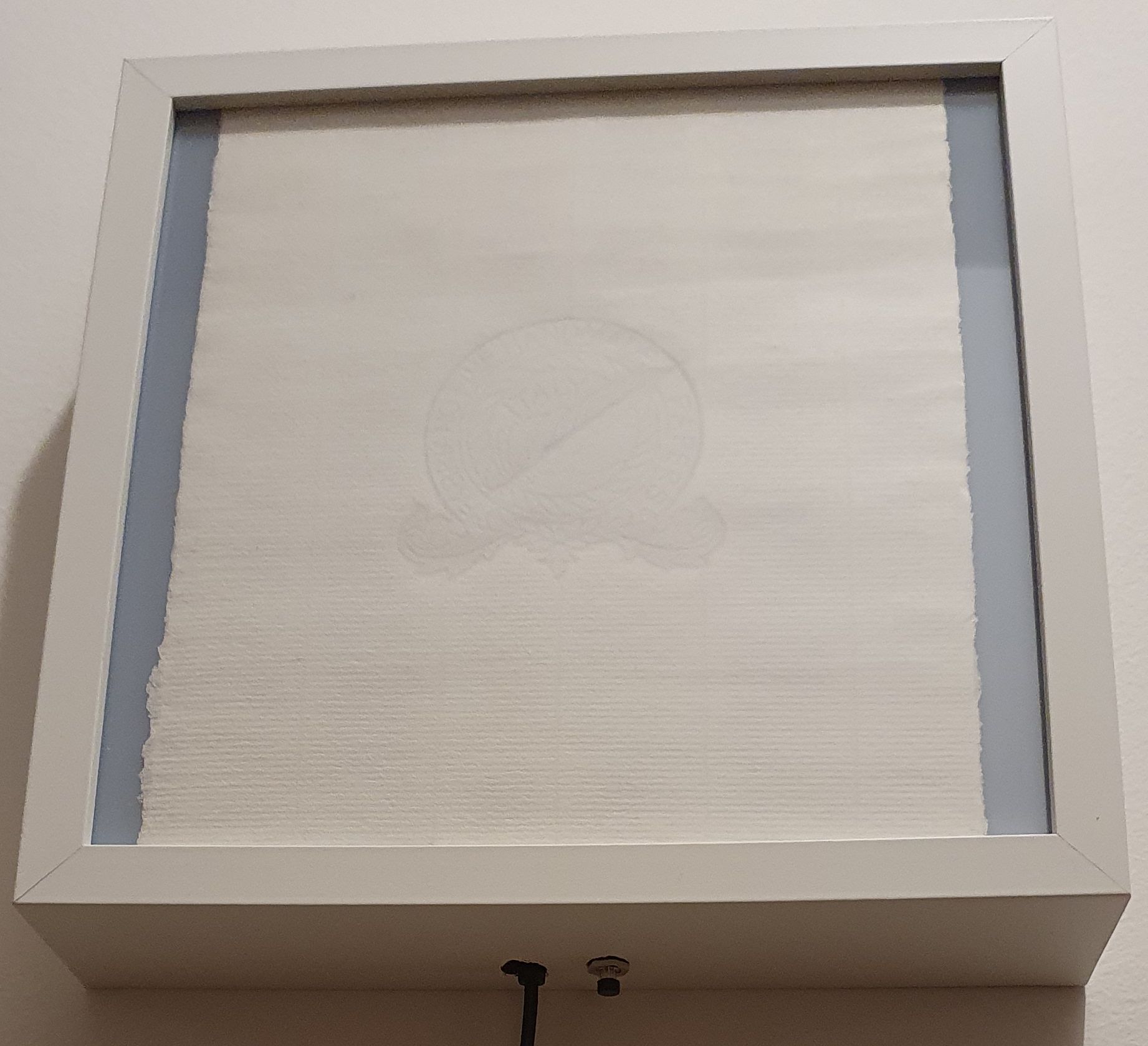
This project was born simply to backlight with a white light an Ikea Ribba 23x23cm frame on which I wanted to show a hand made watermarked paper sheet that I got from the
Fabriano paper museum. As always, the idea soon started evolving on its own...
1) White LEDs with a simple switch and on-board battery
2) ...how to recharge that battery?
Add a DC plug on the board for recharging (I hate lithium batteries, you need a fuel gauge to manage the charge...)
3) ...what if I make it RGB, and with an external supply (without battery charger)?
Add RGB LEDs and microprocessor to control them, take supply from outside with an adapter, change LED topology (4 in series)
4) ...what if I put a pushbutton th start and stop the RGB cycle?
Add pushbutton
5) ...what if I use the pushbutton also to select fixed colors?
Okkkkkkk, the processor can manage some functions after all (note to myself, get a bigger processor with more memory just for safety)
6) ...what if It does also...
Add more complicated functions (timing change, only warm/cool colors, etc...)
7) ...what if I need it for a different frame size or shape?
What the... I had just finished designing the PCB... Add 4 board-to-board connectors to connect together up to 8 boards with a single supply and control point
8) ...what if I want to control everything with a centralized domotic?
This is getting old... Add an RS485 connection for the DMX512A protocol, add software to manage DMX mode (master/slave) and address, redesign all the PCB again
(and this is the third time)
9) ...what next?
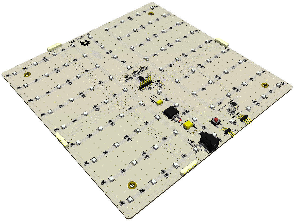
The final specifications are as follows:
Size: 210x210mm, 2-sided FR4 board with standard thickness
Power supply: 12Vdc 500mA, with on-board DC Jack
LED power: 4.5W MAX
LED no.: 80 RGB (20 series of 4)
Functions: color cycles (RGB, RGBW, red always on, green always on, blue always on), fixed colors (24 + white), cycle timing (20s, 60s, 140s, 300s, 600s), DMX master
(output on fixed address 1, 2, 3), DMX slave (selectable address from 1 to 509)
Control mode: 1 NO pushbutton, on-board and remotable
MCU: Microchip PIC16F15323/324/325 (15324 minimum needed for DMX512. 15323 can be used if no DMX function is needed)
The board can be easily ordered from small batch PCB manufacturers (such as
JLC,
Itead or
Seed).
The components are all in SMD technology, but with a bit of dexterity and a decent soldering iron the board can be assembled by hand in a couple of hours.
DOCUMENTS
All the files needed for production are already packed in this zip file, so if you wish
you can simply download it and put it on production. This is the full BOM with the order codes for
Mouser, with the right quantities to make 1 board (or as close as possible) and calculations for multiple boards.
The board can be used in any way while inside the boundaries of the CC-BY-NC-SA license. However, I'd advise you to
give it a careful check if you plan to use it for anything else than an hobbyist testboard.The circuit was tested in all ways possible, but I cannot guarantee
that it will always work in all conditions.
Please don't ask me if I can sell kits or parts or anything else. The answer is NO, because it would not be convenient for you. If you can't assemble the board by yourself, some of the
small batch providers that I linked before can also assemble the boards for you, or you can ask an electronics lab close to your place.
CONSIDERATIONS
About the LEDs
The selected LEDs (Osram Displix P3333) allow for a maximum current of 30mA, 40mA and 50mA respectively on Blue, Red and Green channels, with a typical Vf of 2.85V, 2.05V and 2.65V @20mA.
In theory, the maximum power that can be squeezed out of these LEDs would be about 6.84W, 6.56W and 10.6W. However, leaving other practical issues aside, I've decided to balance the
power in order to not have a huge light difference going from a single color to RGB and back.
The MOSFETs selected to drive the LEDs have a very low RDS in order to avoid heat generation troubles (and anyway the price wasn't high). On the PCB I have provided footprints both for SOT-323
and SOT23 components with a GDS pinout.
About the MCU
The MCU selected for the development board is the PIC16F15325, the bigger of its family with 14 pin package, in order to have the most available memory space to "play" with.
The memory space of a PIC16F15324 is however enough for the full software (DMX included), with enough space to spare to add other functions. If the DMX functionality is not needed,
a PIC16F15323 will be enough.
Considering the low price difference (at least for small volumes), especially comparing it with the total price of the LEDs, I'm not sure using the smaller MCU is worth the trouble.
If, improving the software with more complex functions, even the memory of the PIC16F15325 will not be enough, the PIC16F1832x series pinout is the same (however, the internal organization
changes, so the firmware must be adapted in that case), and the price is still just a bit higher. Basically, with a price increase of about 57% from the smaller to the bigger model,
you can move from 256 to 2048 bytes of RAM, from 3.5 to 28kb of FLASH, add 256 bytes of real EEPROM (the PIC16F1532x series uses a portion of program FLASH memory, "SAF", and reading
or writing it is more complex and also warranted for way less cycles), and from 3 to 7 timers, without changing the PCB.
To recap:
MCU 16F
RAM
FLASH
EEPROM
8/16bit timers
Price each
15323
256
3.5kb/2kw
0 (224b SAF)
1 / 2
0.584€
15324
512
7kb/4kw
0 (224b SAF)
1 / 2
0.652€
15325
1024
14kb/8kw
0 (224b SAF)
1 / 2
0.737€
18323
256
3.5kb/2kw
256b
4 / 3
0.669€
18324
512
7kb/4kw
256b
4 / 3
0.754€
18325
1024
14kb/8kw
256b
4 / 3
0.830€
18326
2048
28kb/16kw
256b
4 / 3
0.915€
Note: all the prices have been taken from Mouser website on december 15, 2020, for a single unit.
About the communications
The board is provided with an RS-485 bidirectional driver. This was thought in order to be able to use it both as slave that as master DMX512A system, in simplex mode. However, by changing
the firmware in the right ways, other functionalities can be added. Some examples are the RDM protocol (ANSI E1.20), or an RS-485 half-duplex serial with any other suitable protocol
that comes into mind. At the moment, the addition of the RDM protocol is not foreseen, as I don't have a master device to test the formware with.